Overview
The description of the standard does not claim to be in absolute compliance with the official documentation, it is our interpretation with its own hardware and software implementation.
The "CCS" standard has an undeniable elegance in its implementation, but also a complexity in its hardware and software.
The main idea of the developers was to provide high-level communication based on the then-existing "TYPE 2" standard for use in transmitting additional parameters for both AC and DC charging systems.


The developers opted for a PLC modem, which provides data transmission over the "CP" line.
Hardware
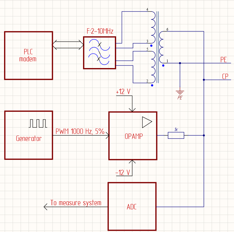
Blocks description:
- PLC modem — the SOC that implements the "HomePlug AV" and IEEE 1901 standard.
- Generator — the circuit that generates a pulse-width signal with a frequency of 1000 Hz and a duty cycle of 5%.
- Opamp — the circuit that generates a signal with an amplitude of +12 V and -12 V coming from the generator.
- Adc — the circuit that measures the amplitude of the generated signal.
The "CP" signal is fed to the electric vehicle's input connector. Depending on the charging session's stage, the vehicle changes the "CP" signal amplitude by connecting load resistors to the "CP" line. The charging system, in turn, reacts to these changes by making appropriate decisions. The "ADC" node must measure the amplitudes of the positive and negative components of the "CP" signal.
Positive component states:
- +12V — the charging connector is not inserted into the vehicle.
- +9V — the charging connector is inserted into the vehicle.
- +6V / +3V — the vehicle is ready for charging.
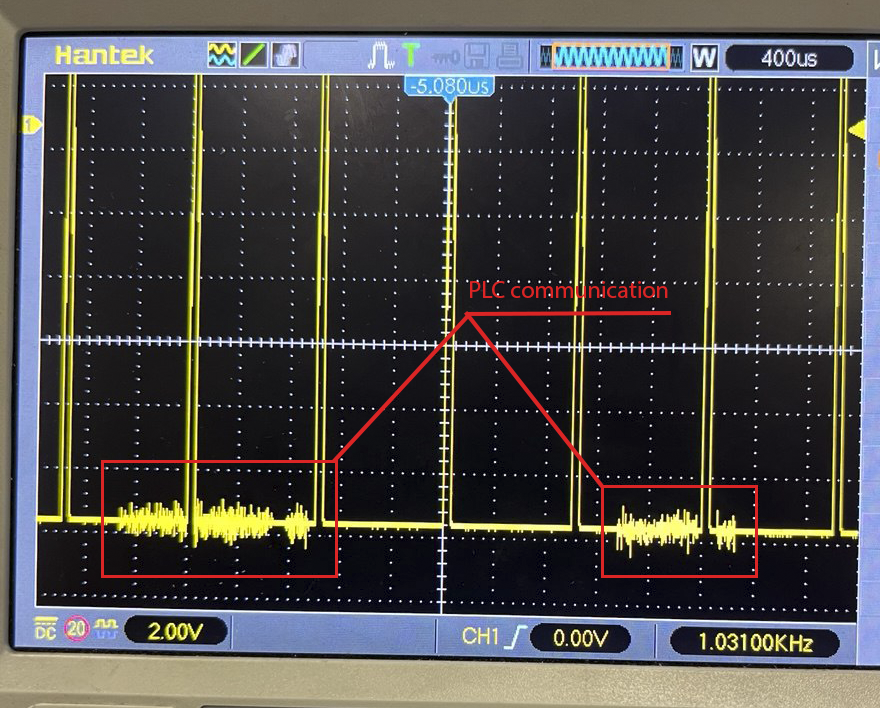
In addition to changing the "CP" signal level, high-level communication occurs. The "CP" signal is used as the carrier frequency. High-level communication is an OFDM modulated signal.
Software
When the charging outlet is inserted into the electric vehicle, the "CP" signal level drops to ~9 V. At this point, the vehicle detects the insertion of the charging connector and prepares to wait for a 5% pulse-width modulation (PWM) signal.
Upon receiving the enable signal, the charging controller should begin generating a PWM signal with a 5% duty cycle.
Upon detecting a PWM signal with a 5% duty cycle on the line, the vehicle initiates high-level communication.
The message exchange process, called SLAC.
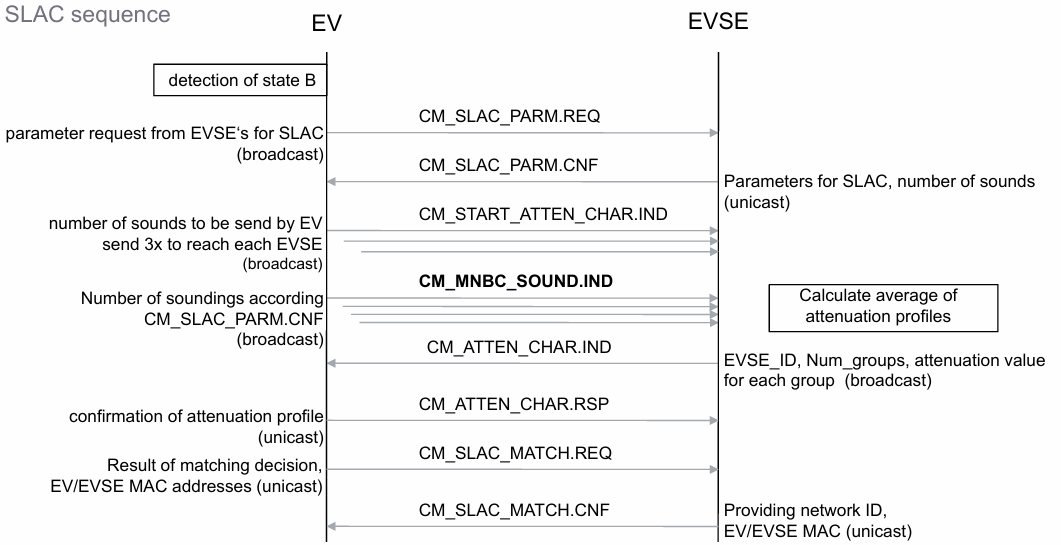
The main objective of this process is to determine whether the charging station is connected to the electric vehicle by measuring the attenuation of the PLC signal. At this stage, we also learn the MAC address of the electric vehicle and communicate our MAC address to it.
After receiving "CM_SLAC_MATCH.CNF" the electric vehicle initiates the procedure of exchanging IPv6 addresses by means of: SDP procedure and ICMPv6 process.


The entire subsequent process of negotiating charging session parameters occurs using EXI (Efficient XML Interchange). This data exchange model, based on defined schemas, enables data compression to ensure more efficient use of communication channel bandwidth.
Charging stages
SupportedAppProtocol processing

At this stage, the electric vehicle reports the supported charging protocols (DIN70121, ISO15118) and standard versions. The controller selects the protocol it will use to charge the electric vehicle.
SessionSetup processing

At this stage, the electric vehicle and charging controller exchange EVCCID and EVSEID values.
ServiceDiscovery processing

At this stage, the charging controller reports available services.
ServicePaymentSelection processing

At this stage based on the provided services and the corresponding payment options by the SECC this message pair allows the transmission of the selected PaymentOption, SelectedServices and related ParameterSets.
ServicePaymentSelection processing
At this stage based on the provided services and the corresponding payment options by the SECC this message pair allows the transmission of the selected PaymentOption, SelectedServices and related ParameterSets.
ContractAuthentication processing

By using the EVSEProcessing parameter, the EVSE can indicate to the EVCC that the processing has not finished but a response message was sent to fulfil the timeout and performance requirements. This allows delaying the V2G Communication Session while fulfilling the performance and timeout requirements.
ChargingParameterDetection processing

At this stage, the electric vehicle and charging controller are configured with charging session parameters (maximum allowable current, minimum allowable voltage, maximum power, etc.)
CableCheck processing

At this stage, the electric vehicle indicates that it is ready for the insulation test. The charging station performs the test using its built-in insulation tester and, upon completion, notifies the electric vehicle of the test status.
PreСharge processing

At this stage, the vehicle requests a specific voltage and current from the charging station, allowing the station's slower power modules to reach the required level in advance.
PowerDelivery processing

The electric vehicle measures the voltage requested during the "Precharge" stage and, upon detecting that the voltage level reaches a specified value, generates a "Power Delivery Request," indicating that it is ready to charge.
Charging processing
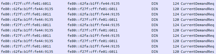
During the charging process, the electric vehicle requests current, the voltage indicates the percentage of charge and a number of other parameters, the charging controller reports the output voltage level, current, and related parameters.
The end of session
The stopping process can be initiated by either the electric vehicle or the charging station.
Stopping a charging session results in the generation of a "PowerDeliveryReq" and the setting of the corresponding flag.

The electric vehicle can then initiate the "Welding Detection" process. Alternatively, it can immediately generate a "Session Stop Req".

The charging station must ensure that the power modules are stopped and all necessary stopping procedures are carried out.