Overview
The description of the standard does not claim to be in absolute compliance with the official documentation, it is our interpretation with its own hardware and software implementation.
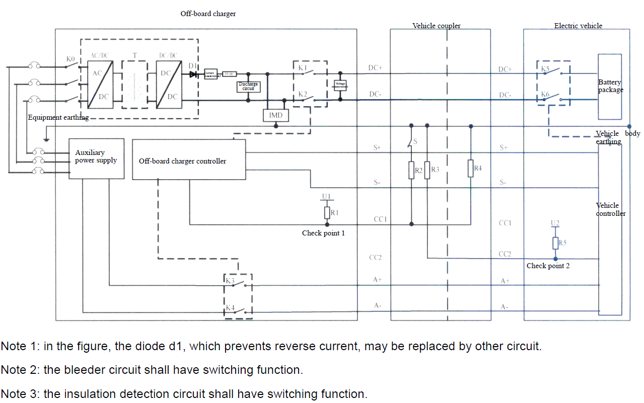
GB/T 20234.3 DC connector specifications:
- Rated voltage: 750 V / 1000 V DC
- Available current: 80 A, 125 A, 200 A, 250 A
- Max power: 250 kW

- S+ / S− — Charging communication CAN_H / CAN_L
- CC1 / CC2 — Charging confirmation post-insertion signalling
- PE — Protective earth full-current protective earthing system
- DC+ / DC- — Main DC power positive / negative
- A+ / A− — Auxiliary DC power 12V +/-5%, 10A
Hardware
Software part
Cable charging standard GB/T 27930 is based on the SAE J1939 network protocol and uses the CAN bus with a point-to-point connection.
This standard is based on the CAN 2.0 specification with an exchange rate of 250 kbit/s, and an 29-bit identifier.
This standard is widely used in modern vehicles as the primary communication standard for vehicle modules.
The protocol is based on the PGN and SPN system. Where the PGN is part of a 29-bit identifier, and the SPN is the payload information located in a specific location within the bit field of an 8-byte message.
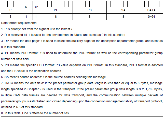
The main drawback of the CAN 2.0 specification is the limited frame length, no more than 8 bytes.
The frame length limitation in the SAE J1939 standard was addressed at the software level. The so-called "Transport Layer" was introduced.
The principle of forming a 29-bit identifier for CAN 2.0B:
const uint8_t addressBMS = 0xF4;
const uint8_t addressCHA = 0x56;
uint32_t id = (priority << 26) | ((pgn | (uint8_t)addressBMS) << 8) | (uint8_t)addressCHA;
/* "pgn", "priority" is specified in the tables of the GB/T 27930-2015 standard. */
Test code for reference:
const uint8_t addressBMS = 0xF4;
const uint8_t addressCHA = 0x56;
const uint8_t START_FRAME_PGN = 0xEC00;
const uint8_t NEXT_FRAME_PGN = 0xEB00;
uint8_t data[8];
const uint8_t CM_RTS = 0x10;
const uint8_t CM_CTS = 0x11;
const uint8_t CM_EndOfMsgACK = 0x13;

/* For example PGN for transmit = 0xFFEB;
   priority = 6;
   data for transmit: payload[28] = {0,1,2,3,4,5,6,7,8,9,10,11,12,13,14,15,16,17,18,19,20,21,22,23,24,25,26,27}
*/
uint16_t pgn = 0xFFEB;
uint8_t payload[28] = {0,1,2,3,4,5,6,7,8,9,10,11,12,13,14,15,16,17,18,19,20,21,22,23,24,25,26,27};

const uint32_t ID_NEXT_FRAME = (priority << 26) | ((NEXT_FRAME_PGN | (uint8_t)addressBMS) << 8) | (uint8_t)addressCHA;

uint16_t size = sizeof(payload);
uint8_t num_of_packets = (size / 7) + ((size % 7) ? 1 : 0);

/* Connection Initiation STEP 1 */
const uint32_t ID_START_FRAME = (priority << 26) | ((START_FRAME_PGN | (uint8_t)addressBMS) << 8) | (uint8_t)addressCHA;
const uint32_t ID_START_FRAME_CTS = (priority << 26) | ((START_FRAME_PGN | (uint8_t)addressCHA) << 8) | (uint8_t)addressBMS;
const uint32_t ID_END_FRAME_ACK = (priority << 26) | ((START_FRAME_PGN | (uint8_t)addressCHA) << 8) | (uint8_t)addressBMS;

data[0] = CM_RTS;
data[1] = (uint8_t)size;
data[2] = (uint8_t)(size >> 8);
data[3] = num_of_packets;
data[4] = 0xFF;
data[5] = (uint8_t)pgn;
data[6] = (uint8_t)(pgn >> 8);
data[7] = 0;
sendMsg(ID_START_FRAME, data, sizeof(data)); // send message to can

/* Step by step we should send 7 bytes of payload, data[0] indicate number of packet, empty bytes we should fill by 0xFF */
/* detailed see below */
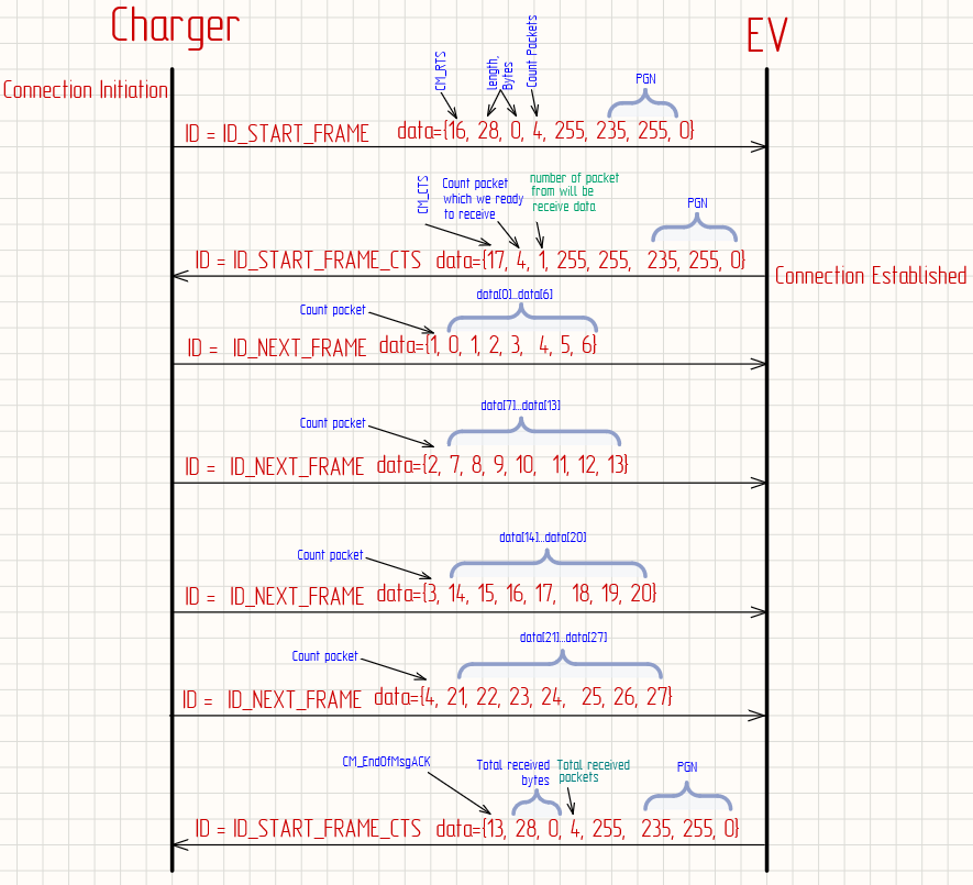
Table 3: Classification of Messages During Charging Handshake Stage
| Message code | Message description | PGN (Dec) | PGN (Hex) | Priority | Data length byte | Message period ms | Source address-destination address |
|---|---|---|---|---|---|---|---|
| CHM | Charger handshake | 9728 | 002600H | 6 | 3 | 250 | Charger → BMS |
| BHM | Vehicle handshake | 9984 | 002700H | 6 | 2 | 250 | BMS → Charger |
| CRM | Charger recognition | 256 | 000100H | 6 | 8 | 250 | Charger → BMS |
| BRM | BMS and vehicle identification message | 512 | 000200H | 7 | 41 | 250 | BMS → Charger |
Table 4: Classification of Messages During Charging Parameter Configuration Stage
| Message code | Message description | PGN (Dec) | PGN (Hex) | Priority | Data length byte | Message period ms | Source address-destination address |
|---|---|---|---|---|---|---|---|
| BCP | Charging parameters of power storage battery | 1536 | 000600H | 7 | 13 | 500 | BMS → Charger |
| CTS | Charger send-time synchronization information | 1792 | 000700H | 6 | 7 | 500 | Charger → BMS |
| CML | Charger's maximum output | 2048 | 000800H | 6 | 8 | 250 | Charger → BMS |