Overview
The description of the standard does not claim to be in absolute compliance with the official documentation, it is our interpretation with its own hardware and software implementation.


The hardware and software implementation of Type 2 and GB/T 18487.1 is almost identical, so we will use the GB/T 18487.1 standard as an example.
Hardware
Hardware part
Charging infrastructure diagram according to GB/T 18487.1 protocol:
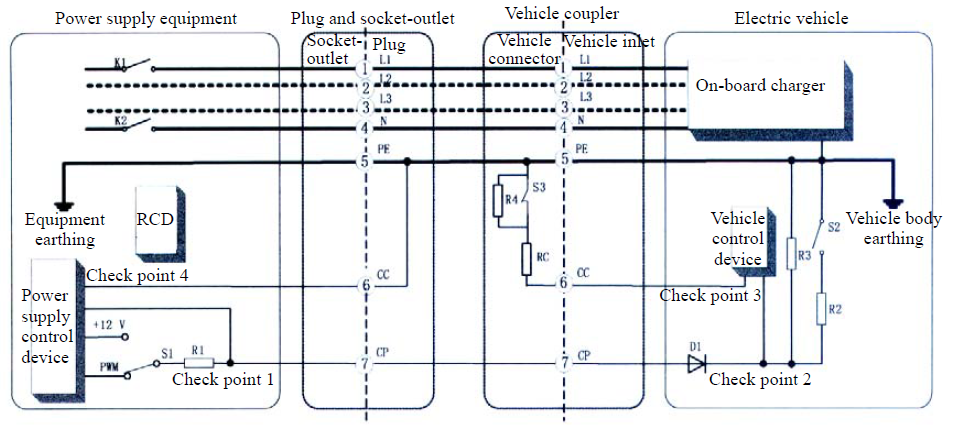
The charging principle is as follows:
When the connector is inserted into the socket, the "CP" signal amplitude changes. This value determines the electric vehicle's readiness to begin a charging session. The charging module, in turn, generates a PWM signal, the duty cycle of which determines the permissible current the charging station can provide.
The "CC/PP" signal is also used to detect the insertion of the charging connector and determine the load capacity of the charging cable.
Description of "CP" signal amplitude values:
| Positive component of signal "CP", V | PWM, ON/OFF | Description |
|---|---|---|
| +12 | OFF | Charger is not ready to transfer an energy, EV not ready to receive energy |
| +12 | ON | Charger is ready to transfer an energy, EV not ready to receive energy |
| +9 | OFF | Charger is not ready to transfer an energy, EV not ready to receive energy |
| +9 | ON | Charger is ready to transfer an energy, EV not ready to receive energy |
| +6 | OFF | Charger is not ready to transfer an energy, EV ready to receive energy |
| +6 | ON | Charger is ready to transfer an energy, EV ready to receive energy |
| +3 | OFF | Charger is not ready to transfer an energy, EV ready to receive energy |
| +3 | ON | Charger is ready to transfer an energy, EV ready to receive energy |
| 0 | - | ERROR |
Software
Program part
The software implementation consists only of measuring the state of the "CP" and "PP" signals and generating a PWM signal depending on the permissible current.